Circuit diagrams and symbols

Symbols
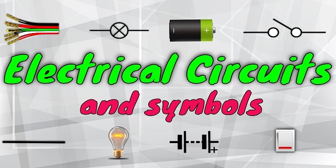
The selection of symbols given in Chapter 3, is intended as a guide to some of those in use. Some manufacturers use their own variation but a standard is developing. The idea of a symbol is to represent a component in a very simple but easily recognizable form. The symbol for a motor or for a small electronic unit deliberately leaves out internal circuitry in order to concentrate on the interconnections between the various devices.
Examples of how these symbols are used are given in the next three sections, which show three distinct types of wiring diagram. Due to the complexity of modern wiring systems it is now common Figure 4.29 The vehicle dual data bus system Figure 4.28 Block diagram of control system for low beam lamps 98 Automobile electrical and electronic systems practice to show just part of the whole system on one sheet. For example, lights on one page, auxiliary circuits on the next, and so on.
Conventional circuit diagrams
The conventional type of diagram shows the electrical connections of a circuit but makes no attempt to show the various parts in any particular order or position. Figure 4.30 shows an example of this type of diagram.
Layout or wiring diagrams
A layout circuit diagram makes an attempt to show the main electrical components in a position similar to those on the actual vehicle. Owing to the complex circuits and the number of individual wires, some manufacturers now use two diagrams – one to show electrical connections and the other to show the actual layout of the wiring harness and components. Citroën, amongst others, has started to use this system
Terminal diagrams
A terminal diagram shows only the connections of the devices and not any of the wirings. The terminal of each device, which can be represented pictorially, is marked with a code. This code indicates the device terminal designation, the destination device code and its terminal designation and, in some cases, the wire color code
Current flow diagrams
Current flow diagrams are now very popular. The idea is that the page is laid out such as to show the current flow from the top to the bottom. These diagrams often have two supply lines at the top of the page marked 30 (main battery positive supply) and 15 (ignition controlled supply). At the bottom of the page is a line marked 31 (earth or chassis connection).
The system also has the benefit of self-diagnosis for all functions, including engine management, making the OBD (on-board diagnostics) unit even more important than before. Diagnosis is easier, as is servicing. Any information about a fault or malfunction is passed on to the driver by indicator lamps and a message display in the instrument cluster. All the cables in the system are fitted in well protected cable ducts. The multiplex system in each car is programmed according to model specifications and fitted options.
With its comprehensive coverage and detailed analysis, it offers a valuable resource for trend enthusiasts. By providing accurate and timely information, Trendsactually keeps its audience ahead of the curve. Whether you’re a fashionista, a tech enthusiast, or simply someone who appreciates staying current, Trendsactually has something for everyone.


