Electrical wiring, terminals and switching
Cables
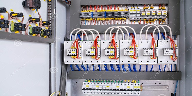
Cables used for motor vehicle applications are almost always copper strands insulated with PVC. Copper, beside its very low resistivity of about has ideal properties such as ductility and malleability. This makes it the natural choice for most electrical conductors PVC as the insulation is again ideal, as it not only has very high resistance, the order of 1015 m, but is also very resistant to petrol, oil, water and other contaminants
trol, oil, water and other contaminants. The choice of cable size depends on the current drawn by the consumer. The larger the cable used then the smaller the volt drop in the circuit, but the cable will be heavier. This means a trade-off must be sought between the allowable volt drop and maximum cable size. Table 4.1 lists some typical maximum volt drops in a circuit.
Colour codes and terminal designations
As seems to be the case for any standardization, a number of colour code and terminal designation systems are in operation. For reference purposes I will just make mention of three. First, the British Standard system (BS AU 7a: 1983). This system uses 12 colours to determine the main purpose of the cable and tracer colours to further define its use.
that there is no correlation between the ‘Euro’ system and the British standard colour codes. In particular, note the use of the colour brown in each system. After some practice with the use of colour code systems the job of the technician is made a lot easier when fault-finding an electrical circuit.
Harness design
The vehicle wiring harness has developed over the years from a loom containing just a few wires, to the looms used at present on top range vehicles containing well over 1000 separate wires. Modern vehicles tend to have wiring harnesses constructed in a number of ways. The most popular is still for the bundle of cables to be spirally wrapped in nonadhesive PVC tape. The tape is non-adhesive so as to allow the bundle of wires to retain some flexibility
Printed circuits
The printed circuit is used almost universally on the rear of the instrument pack and other similar places. This allows these components to be supplied as complete units and also reduces the amount and complexity of the wiring in what are usually cramped areas
The printed circuits are constructed using a thin copper layer that is bonded to a plastic sheet – on both sides in some cases. The required circuit is then printed on to the copper using a material similar to wax. The unwanted copper can then be etched away with an acid wash. A further layer of thin plastic sheet can insulate the copper strips if required.
shows a picture of a typical printed circuit from an instrument panel and gives some indication as to how many wires would be required to do the same job. Connection to the main harness is by one or more multiplugs.


