introduction
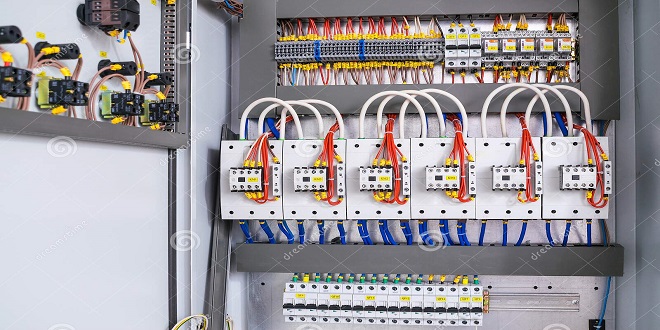
The complexity of modern wiring systems has been increasing steadily over the last 25 years or so and, in recent years, has increased dramatically. It has now reached a point where the size and weight of the wiring harness is a major problem. The number of separate wires required on a top-of-the-range vehicle can be in the region of 1500! The wiring loom required to control all functions in or from the driver’s door can require up to 50 wires,
the systems in the dashboard area alone can use over 100 wires and connections. This is clearly becoming a problem as, apart from the obvious issues of size and weight, the number of connections and the number use a common data bus. This would allow communication between modules and would make the information from the various vehicle sensors available to all sensors
Taking this idea a stage further, if data could be transmitted along one wire and made available to all parts of the vehicle, then the vehicle wiring could be reduced to just three wires. These wires would be a mains supply, an earth connection and a signal wire. The idea of using just one line for many signals is not new and has been in use in areas such as telecommunications for many years. Various signals can be ‘multiplexed’ on to one wire in two main ways – frequency division and time division multiplexing. Frequency division is similar to the way radio signals are transmitted. It is oversimplifying a complex subject, but a form of time division multiplexing is generally used for transmission of digital signals.
Bosch CAN (Controller Area Networks)
Bosch has developed the protocol known as ‘CAN’ or Controller Area Network. This system is claimed to meet practically all requirements with a very small chip surface (easy to manufacture, therefore cheaper). CAN is suitable for transmitting data in the area of drive line components, chassis components and mobile communications.
It is a compact system, which will make it practical for use in many areas. Two variations on the physical layer are available that suit different transmission rates. One is for data transmission of between 100 K and 1 M baud (bits per second), to be used for rapid control devices. The other will transmit between 10 K and 100 K baud as a low-speed bus for simple switching and control operations
CAN signal format
The CAN message signal consists of a sequence of binary digits (bits). A voltage (or light in fibre optics) being present indicates the value ‘1’ while none present indicates ‘0’. The actual message can vary between 44 and 108 bits in length. This is made up of a start bit, name, control bits, the data itself, a cyclic redundancy check (CRC) for error detection, a confirmation signal and finally a number of stop bits